The A330-
Aerodynamics
The aerodynamics model is a full stability derivative model for the A330-
FMGS
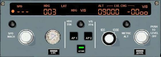
The Autopilot, Auto throttle and FMC functions of the FMGS are modelled. The simulator can fly a entered flight plan and navigate from take off to approach or G/A. Almost all possible MCDU pages are available, including all flight entry type pages, vertical revision pages and lateral revision pages etc. The MCDU part of this simulation is integrated into the Airbus MCDU Aid. The A/P and A/THR have been included in the Airbus FMGS Aid.
Radio Altimeter
The radio altimeter model accounts for the aircraft pitch and roll attitude and passes
on valid radio altimeter values for -
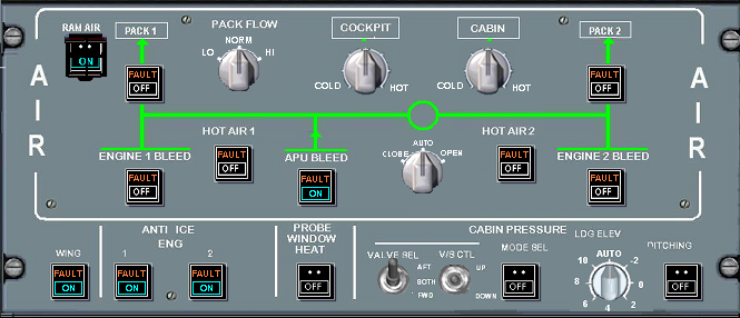
The Pneumatics model interfaces with the overhead air panel and models the pressurisation and temperature of the cabin. The model accounts for open doors, FMGC landing altitude, status of the packs, and all control inputs at the air panel.
The pressurisation schedule is slightly different from the Airbus, as the simulator will not doubt be flown in a non normal (takeoff, climb, cruise, approach and land) manner. The model allows sensible pressurisation of the cabin for continuous climb and descent manoeuvring . When flown as a route from take off to landing, the pressurisation schedule will be similar to the airbus system.
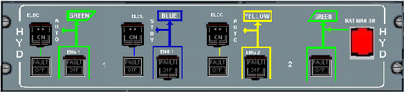
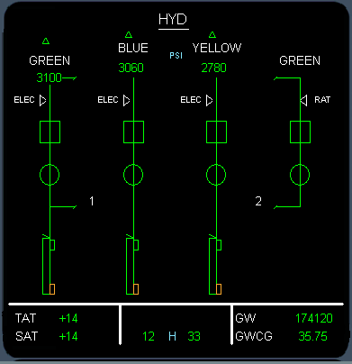
The Hydraulics model completely simulates the 3 separate hydraulic systems, Green, Yellow and Blue of the A330. It models the electrical pumps and the engine driven hydraulic pumps. The system pressures respond to the control surface movements. All controls on the overhead hydraulic control panel function, and the correct system responses occur. The RAT input is currently not modelled.
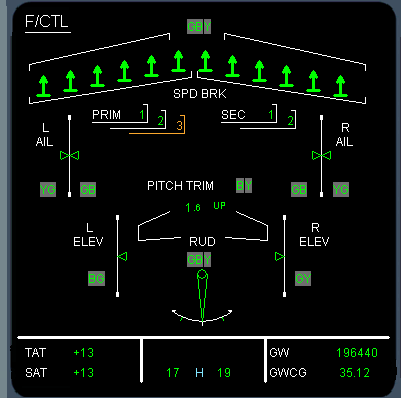
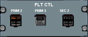
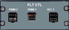
The flight control simulation covers the Airbus Fly By Wire computers and their 3 control laws, Normal, Direct and alternate. The Flight Controls model take input from the joy stick or Autopilot and through the relevant control law drive the surfaces, elevator, aileron, spoilers and rudder. The model also includes the Alpha protection and over speed protection control laws and computes the limit speeds for the Primary Flight Display.
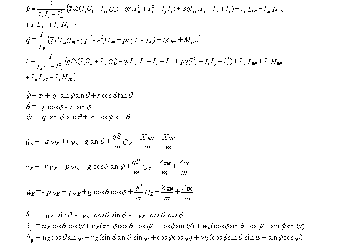
Equations Of Motion
At the heart of the aircraft simulation is the 6 DOF quaternion equations of motion. These accept inputs of aerodynamic forces and moments, ground reaction forces and moments and engine forces and moments. In addition the model allows for step changes in wind and altitude and position. A WG85 type geographical model computes actual latitude and longitude for the rest of the simulation
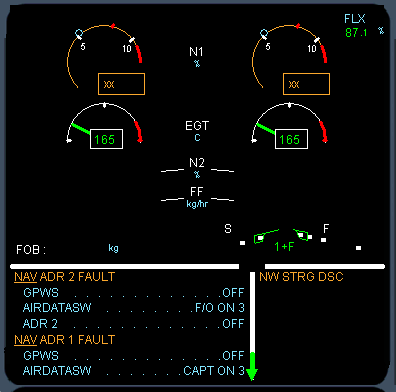
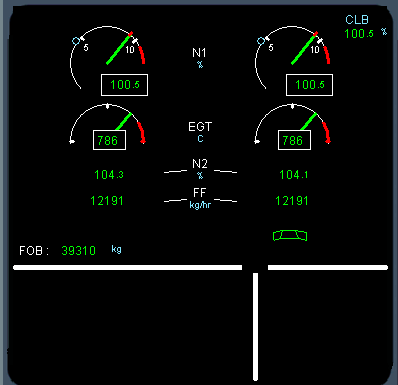
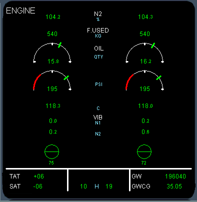
The engine model is a simple LFI type model of a 2 spool N1 type hi bypass fan engine. The actual engine parameters of a CF6 or RR Trent engine are used to scale the outputs of the simple model to produce representative thrust, EGT, and fuel flow parameters. A FADEC model interfaces the engine to the throttle box model, and passes data to the displays
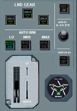
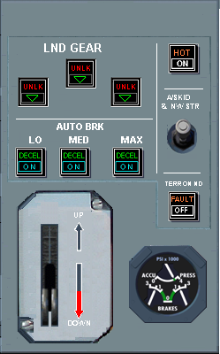
The Auto brake models allows the automatic activation of main gear wheel brakes for touch down and rejected take off. The auto brake values are determined from the A/B selection on the landing gear panel. The Auto brake models also sets the "Decel" light on the panel. When the speed brake lever is fitted the A/B model will be armed using the status of the speed brake handle
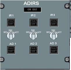
The ADIRU model is split into the traditional Air Data System (ADS) model and the Inertial Reference system (IRS) model.
The ADS has a complete model of 3 Air Data computers and 3 Pitot static models, which can include varying static error to allow for slightly different readings.
The 3 Pitot static models fully account for any ground static pressure variance.
The IRS models 3 IRU, which correctly model the sensed aircraft accelerations and velocities at their location in the airframe. The ADS and IRU correctly respond to inputs form the over head panel and from the MCDU
Weight and Balance (WBC)
The weight and balance model computes the aircraft mass, and cg as fuel is used and passes this information onto the FMGS. Its input is the inertia model located in the Equations of Motion. The WBC values are used by the FMGS to control fuel Xfr commands to maintain reasonable Cg.
The FMGS interfaces withe the fuel model to control the CG value during flight. The fuel model uses forward and aft fuel transfers to effect this control.
Phase Of Flight (POF)
Through out the avionics models there is a need to compute the POF for use in system logic. This model produces one generic POF and two specific POFs, one for the Warning Computer and one for the FMGS. The POF can be set accordingly when performing repositions etc.
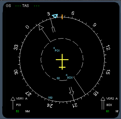
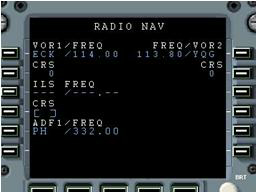
Navigation Radios
The Navigation radio models the ability to tune and receive VOR or NDB information and display the raw data on the displays and pass back positional data to the FMGS. The data set for the station data contains information about the reception range of each station, which sis used to determine if reception is possible. Line Of Sight calculations are used to determine the current range to station. Terrain occultation is not done.
Lights
The Light model computes the lighting discretes that would be needed by a visual interface. It also provides the electrical loading input to the electrical system. The overhead light switches are used as input.
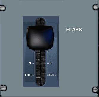
Flap / Slat system
This model encompasses the flaps, slats and their respective drive mechanisms and control unit. the model computes flap load relive and schedules the flaps according to the flap handle setting and the aircraft POF. The model responds correctly to hydraulic supply availability of the Green and Yellow systems. The model also interfaces with the Flight Controls System to produce the Alpha Lock function.
The simulation uses a central warning system model which ultimately produces the
ECAM messages on the EWD and auto-
The text message and its control status (underlined, indented, color, associated messages etc) is sent to the display so only one model needs to be updated as more ECAM messages and possibility of ECAM messages occurs
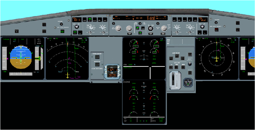
Displays
To allow for the possibility of using other displays systems and in accordance to
the hardware design, the whole of the interface to the PFD, ND, EWD and System displays
is performed in one model. This one model collects the data from the simulated avionics
buses and discrete information from the models and packages the information ready
to send on Ethernet to any other PC capable of producing a Display. Each Display
data is a single package. Each display system package has a header indicating the
type of display and therefore allows the end user to interrupt the package data.
In this way the physical left ND can show the left PFD, simply by changing the data
package. For some displays, there are various "pages" such as the system display
and the Navigation Display. The Page header information within the data package allows
the end user to interpret the information correctly. thus there is only one ND data
package sent (to each side), but it may contain the VOR, or Plan information depending
upon the knob selection in the cockpit. Pilot and Co-
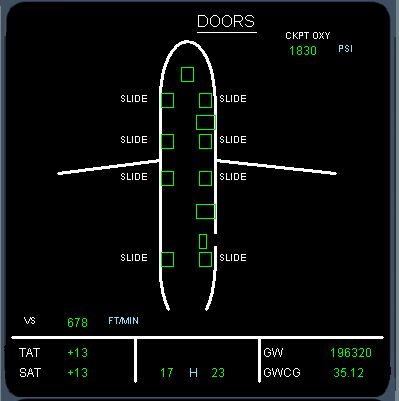
Doors
There is a simple model of the doors to allow the Doors Page on the system Display and the pressurisation model to function. This allows the Yellow hydraulic system to operate on the ground using the electrical pump for the opening and closing of the cargo door.
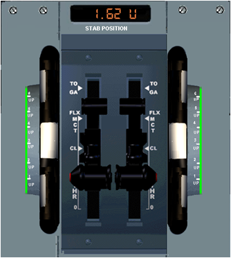
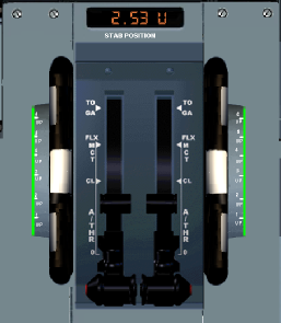
Stab Trim (FAC)
The stab trim model simulates the auto stab trim function using inputs from the Flight Control system. The stab trim model will be able to accept manual input when a trim wheel is fitted in the cockpit
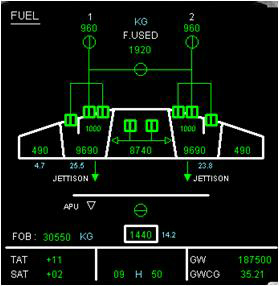
The fuel system model consist of fuel tanks, pumps, valves and pipes. A full model
of the A330-
Yaw Damper (FAC)
The yaw damper model is required at low speed to stabilise the Dutch roll tendency of the aircraft. It is connected in series to the parallel rudder inputs from the flight controls system.
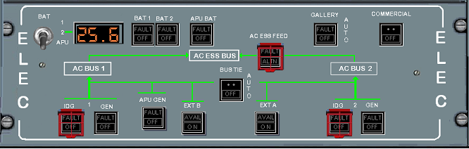
A full A330-
The system correctly responds to the inputs from the overhead electrical panel, APU, ground power etc.
Emergency generator is not yet modeled, but the emergency electrical panel is functional.
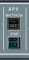
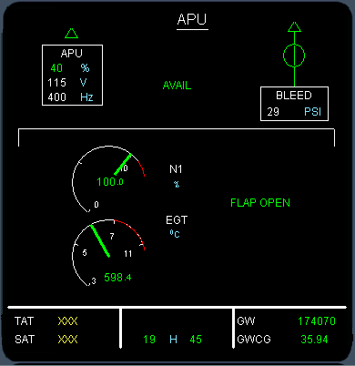
A generic APU model simulates the A330 APU functions, from start through to shut down. This includes APU door opening, N1, EGT changes for Bleed or generator on/off, 120 sec shut down time, and realistic EGT and N1 values for display.
Throttle box
A throttle box model exits to connect the engine FADECs to the either the Auto throttle function of the FMGS or to the actual throttles. All thrust lever detent positions modelled, such as IDLE, CL, MCT/FLEX and TOGA
The landing gear model simulates the landing gear system performance, up/down transitions,
display indications, wheel temperatures etc. In addition the landing gear model also
contains the appropriate ground re-
|
Reservoir quantity |
Fully modeled, with effects of system usage etc. |
|
Reservoir Overheat |
Modeled as a malfunction |
|
Reservoir Low Air |
Effects of loss of bleed air modeled |
|
System pressure |
Realistic effects of usage, flap changes landing gear movement etc. |
|
Shut Off Valves |
Correctly modeled with Green system being automatic |
|
Engine driven pumps |
Full integration with the electrical system and the overhead panel |
|
Electrical driven pumps |
Full integration with the electrical system and the overhead panel |
|
Hydraulic ECAM messages |
Low system pressure, Low Air, amber warnings. Dual system failure Red warnings modeled |
|
RAT |
Not modeled |
|
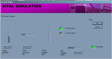
A/P |
Fully modeled, sensor conditioned, with engage and disconnect logic . |
|
A/THR |
Fully modeled, sensor conditioned, with engage and disconnect logic . |
|
Pitch Modes |
ALT *, ALT, OP CLB, CLB, OP DES, DES, SRS, V/S, FPA, G/S all modeled |
|
Roll Modes |
HDG,NAV,RNW,RNW TRK,TRACK,LOC all modeled |
|
A/THR modes |
SPEED, MACH, IDLE, THRUST all modeled |
|
FCU |
Fully modeled except metric alt |
|
CAT 1,2,3 ILS |
Fully modeled, with G/S, LOC, LAND, FLARE, ROLL OUT modes all functioning |
|
PFD indications |
Target values, Flight Mode Annunciations, F/D . FPV all modeled |
|
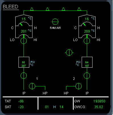
Bleed System |
Fully modeled for APU bleed and engine bleed. Ground air not modeled. |
|
PACKS |
Fully modeled, integrated with the PACK FLOW knob and system configuration |
|
Air Conditioning |
Fully modeled and integrated with overhead AIR panel. |
|
Ventilation |
Partially modeled, avionics ventilation model is representative |
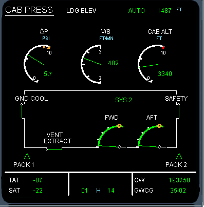
|
Pressurization |
Fully modeled, integrated with FMGS landing altitude and overhead panel for manual control |
|
ECAM |
Fully modeled System display pages of BLEED. COND and PRESS and Crz page values |
|
|
|
|
|
|
|
Normal C Laws |
Fully modeled, attitude, G values limitations and speed protection included |
|
Alternate C Laws |
Fully modeled |
|
Direct C Laws |
Fully modeled |
|
Pitch |
All pitch laws implemented and integration with the A/P |
|
Roll |
All roll laws implemented and integration with the A/P |
|
Yaw |
Yaw damper and integration with the A/P modeled |
|
Alpha speeds |
Normal and Direct alpha speed protection and PFD indication modeled |
|
Over speed protection |
Over speed protection for Gear, Flap, VMO, MMO implemented |
|
Side Stick integration |
Flight Controls integrated with Commercial Joy Sticks, Offsets and scaling catered for |
|
ECAM |
Full system display for Flight Controls modeled |
|
Cockpit |
Full integration with the overhead panels for flight controls |
|
Stab Trim |
Fully modeled, both manually and automatic. Auto stab trim set when performing repositions |
|
Flap Aileron offset |
Not modeled Aileron neutral position does not change for flap settings |
|
|
|
|
|
|
|
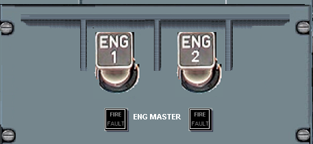
Automatic Engine Start |
Fully modeled, IGN settings, APU bleed input, automatic fuel flow at N2 % values. |
|
Manual engine start |
Fully modeled. Overhead panel MAN buttons modeled. |
|
Engine Fire buttons |
Fully modeled |
|
ECAM |
Engine System display fully modeled |
|
|
|
|
|
|
|
|
|
|
Auto Brake selection |
Fully modeled, MIN, MED and MAX |
|
Speed Brake integration |
Fully integrated, auto brakes function at ground spoiler deployment. |
|
RTO |
Fully modeled, MAX braking fully functioning. DECEL indications modeled |
|
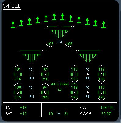
Brake Heating |
Brake heating effects modeled and HOT BRAKE indications appear when above 300 Deg C |
|
Brake Cooling |
Brake Fan modeled and integrated |
|
Blue Hydraulic system |
Fully integrated with accumulator model |
|
Green Hydraulic system |
Fully integrated |
|
Triple indicator |
Partially modeled, Brake pressure indications are only off and on. |
|
3 impendent systems |
Fully modeled, X.Y Z offsets from CG . |
|
Air data buttons |
Fully integrated with panel and displays. |
|
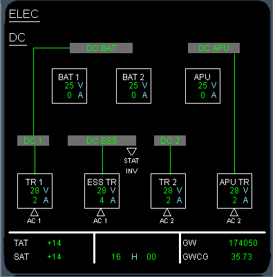
Electrical conditioning |
On Batteries, electrical busses etc fully modeled |
|
MCDU pages |
Fully integrated to the MCDU Data pages |
|
Alignment |
Fully integrated with the INIT MCDU page |
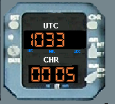
Clock
There is a simple clock model that integrates at the simulation rate to provide UTC time to all avionics. The clock can initialised either to a simulation scenario tome or to current UTC time. The main user of the clock is the FMGS for ETA predictions and RTA predictions
|
UTC |
UTC time synchronized to current world time |
|
Stop watch |
Integrated to Chrono button on glare shield |
|
Chrono on ND |
Stop watch time indicated on ND |
|
Auto Nav Selection |
NDB/VOR radio stations used for navigation automatically updated through the flight |
|
RAD NAV MCDU |
Operation RAD NAV MCDU page. ILS, VOR, ADF and auto selection available |
|
ND interfaces |
Radio navigation indications on the ND |
|
ILS |
Fully integrated to the Auto flight system for Auto land |
|
Flap handle panel |
All flap settings available |
|
EWD indications |
Full Flap/Slat indications on the EWD |
|
Hydraulic interfaces |
Fully integrated with the Hydraulic system |
|
Alpha lock |
Alpha slat lock modeled |
|
Flap load relief |
Automatic flap load relief modeled |
|
On ground refueling |
Fully modeled |
|
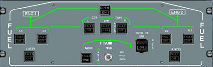
Center tank transfers |
Fully modeled |
|
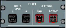
Outer to Inner transfers |
Automatic and manual modeled |
|
Forward / Aft transfers |
Automatic and manual modeled, fully integrated to MCDU/FMGS |
|
Fuel panel |
Fully integrated to overhead fuel panel |
|
Fuel plant model |
All valvles, pumps, tanks, pipes fully modeled |
|
Fuel jettison |
Fully modeled |
|
AC electrical circuits |
Fully modeled |
|
DC electrical circuits |
Fully modeled |
|
External power |
Fully modeled |
|
APU generator |
Fully modeled |
|
Engine generators |
Fully modeled |
|
Emergency generator |
Not yet implemented |
|
Load shedding |
Fully modeled |
|
Landing Gear panel |
Fully modeled and integrated with the landing gear model |
|
Triple indicator |
Shows the brake applied pressure as on/off. |
|
Warnings |
Fully integrated with the ECAM to display landing gear warnings. |
|
Auto brakes |
Fully modeled, Max. Med and Min |
|
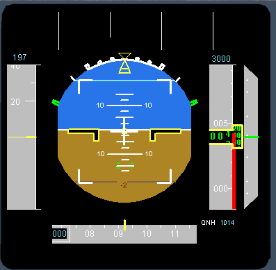
System display |
Fully modeled |

|
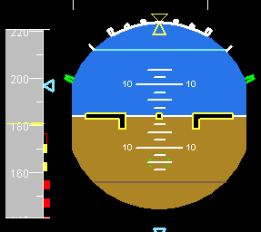
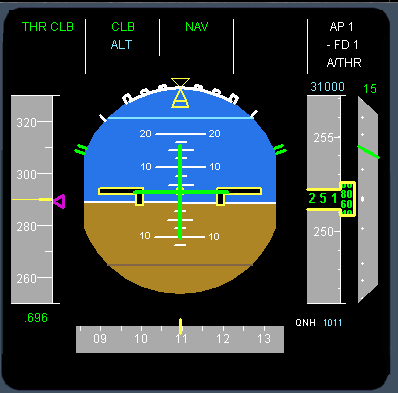
Spd Tape |
Fully modeled |
|
Hdg Tape |
Fully modeled |
|
Alt Tape |
Fully modeled |
|
V/S indicator |
Fully modeled |
|
ADI ball |
Fully modeled |
|
F/D |
Fully modeled and integrated with the NAV Control panel |
|
FMA |
Fully modeled and integrated to the FMGS |
|
ILS |
LOC and G/S scales fully modeled |
|
Vertical Deviation |
Fully modeled and integrated with the MCDU |
|
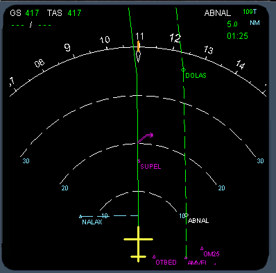
Rose |
Fully modeled |
|
Arch |
Fully modeled |
|
Plan |
Fully modeled |
|
VOR |
Fully modeled |
|
ILS |
Fully modeled |
|
Engine |
Fully modeled |
|
Range |
Fully integrated with the Nav Control Panel |
|
Selections |
Fully integrated with the Nav Control Panel |
|
Data |
Fully integrated with the Nav Control Panel |
|
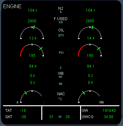
N1 |
Fully modeled |
|
EGT |
Fully modeled |
|
N2 |
Fully modeled |
|
Fuel Flow |
Fully modeled |
|
Flap indicator |
Fully modeled |
|
FOB |
Fully modeled |
|
ECAM |
Integrated with all the other aircraft systems |
|
Engine |
Fully modeled |
|
Cruise |
Fully modeled |
|
APU |
Fully modeled |
|
Bleed |
Fully modeled |
|
Pressure |
Fully modeled |
|
Air Con |
Fully modeled |
|
CB |
Fully modeled |
|
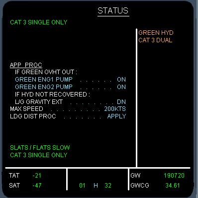
Status |
Fully modeled |
|
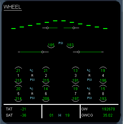
Wheel |
Fully modeled |
|
Flt Controls |
Fully modeled |
|
Fuel |
Fully modeled |
|
Hydraulics |
Fully modeled |
|
Electrical AC |
Fully modeled |
|
Electrical DC |
Fully modeled |
|
Doors |
Fully modeled |
|
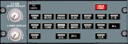
ECAM Panel |
Fully integrated |
